


News from Chauvin Arnoux Metrix
 En savoir plus
25 March 2024
New 2024 catalogues
Need a measuring instrument? We’re sure to have what you’re looking for: testers, Voltage Absence Testers, multimeters, oscilloscopes, power loggers, etc. Check out our 2024 catalogues.
 En savoir plus
20 February 2024
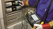
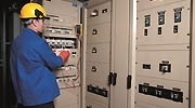
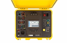
Communicating machine testers
Surveillez à distance vos mesures, restez en sécurité, grâce à l'affichage distant des contrôleurs machines CA 6161 & CA 6163.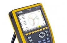 En savoir plus
23 January 2024
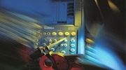
New functionality for the CA 8345 QualiStar power quality analyser !
Nouvelle fonctionnalité de l’analyseur STAR des réseaux électriques CA 8345 QualiStar ! La Star de la sécurité de vos réseaux !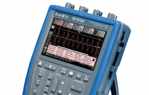 En savoir plus
30 November 2023
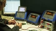
Oscilloscopes with isolated channels
Chauvin Arnoux's oscilloscopes with isolated channels are equipped with a patented digital technology.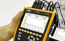 En savoir plus
03 November 2023
New features for the QualiSTAR 2!
Optimized touch HMI, extended range for harmonics measurements and communication by the power quality analyser using a smartphone are just some of the new technological features integrated into the new version of our CA 8345 model.Chauvin Arnoux Metrix is certified ISO 9001 and ISO 14001 for all its sites